Winding distribution factor: why spreading conductors costs EMF
Distribution factor kd measures the penalty for placing a phase's conductors in several slots rather than one. The conductors generate slightly out-of-phase EMFs that add as phasors — their vector sum is always less than their arithmetic sum, and kd is the ratio between the two.
The phase belt: how slots are assigned to a phase
In a three-phase AC machine, the stator slots are divided among three phases — A, B, and C. Under each rotor pole, each phase occupies a phase belt: a group of consecutive slots whose conductors are all connected in series for that phase.
The number of slots in each phase belt is called slots per pole per phase, q:
When q = 1, every slot of a phase belt contains conductors from only one phase, and they are all at the same electrical angle — a concentrated winding. When q > 1, the phase belt spans q consecutive slots, each at a slightly different electrical angle — a distributed winding. Almost all large AC machines use distributed windings.
12 slots, 4 poles, 3 phases: q = 12 / (4 × 3) = 1 — concentrated winding, one slot per phase belt.
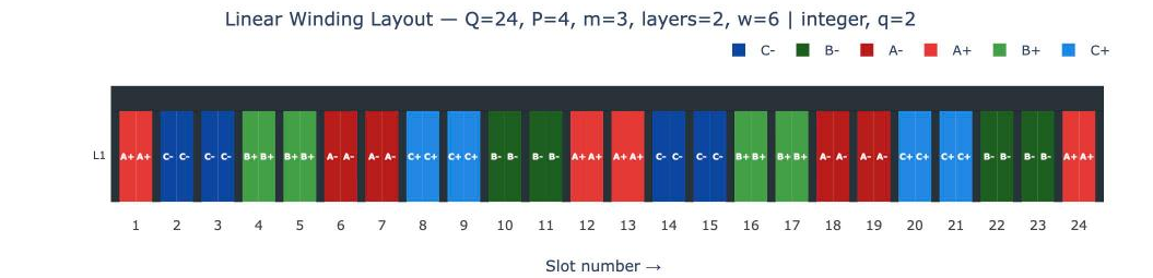
24 slots, 4 poles, 3 phases: q = 24 / (4 × 3) = 2 — distributed winding, two slots per phase belt.
Electrical angle per slot and the phase belt spread
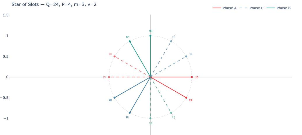
Every slot carries an EMF phasor whose phase angle is set by the slot's electrical position. Adjacent slots differ by the electrical angle per slot α:
The q slots of a phase belt are consecutive, so their EMF phasors span a total arc of (q − 1) × α in electrical degrees. The first slot of the belt is the reference at 0°; the last slot is at (q − 1) × α. Each slot's phasor is offset from its neighbour by exactly α.
α = (4/2) × (360°/24) = 2 × 15° = 30° per slot
Phase belt A under pole 1: slot 1 → 0°, slot 2 → 30°
The two EMF phasors are separated by 30°. They are nearly — but not exactly — in phase.
Why phasor addition gives less than arithmetic addition
If both conductors of phase A's belt were in the same slot, their EMFs would be perfectly in phase and their series sum would equal 2 × E1 — the arithmetic total. But they are not in the same slot; one is at 0° and the other at 30°. Adding two phasors of equal magnitude E1 separated by 30°:
Phasor 1: E1 ∠0° Phasor 2: E1 ∠30°
Resultant magnitude = 2 E1 cos(30°/2) = 2 E1 cos(15°) = 2 × 0.9659 E1 = 1.932 E1
Arithmetic sum would be: 2 E1 = 2.000 E1
Distribution factor: kd = 1.932 / 2.000 = 0.966
The 3.4% reduction is the price of distribution. In exchange, the winding benefits from lower MMF harmonics, shorter end-turns per conductor, and a more sinusoidal air-gap flux — advantages that far outweigh the small EMF penalty in most machine designs.
The distribution factor formula
The general result for q equally spaced phasors, each separated by α, follows from the geometry of a regular polygon inscribed in a circle. The vector sum of q unit phasors with step angle α equals:
The arithmetic sum of q unit phasors is simply q. Dividing gives the distribution factor:
Note that when q = 1, sin(α/2) / (1 · sin(α/2)) = 1 exactly — a concentrated winding has no distribution penalty. As q increases, kd falls, but slowly: doubling q from 1 to 2 only reduces kd from 1.000 to around 0.966 for typical slot/pole ratios.
Worked example: three machines, same pole count
Consider three 4-pole, 3-phase machines with different slot counts. All share P=4, m=3, so α = 2 × (360°/Q). Increasing Q increases q and distributes the winding more finely.
α = (4/2) × (360°/12) = 60°
q = 12 / (4 × 3) = 1
kd = sin(1 × 60°/2) / (1 × sin(60°/2)) = sin(30°)/sin(30°) = 1.000
No distribution penalty — all phase conductors under each pole are in one slot.
α = (4/2) × (360°/24) = 30°
q = 24 / (4 × 3) = 2
kd = sin(2 × 30°/2) / (2 × sin(30°/2)) = sin(30°) / (2 × sin(15°)) = 0.500 / (2 × 0.2588) = 0.966
α = (4/2) × (360°/36) = 20°
q = 36 / (4 × 3) = 3
kd = sin(3 × 20°/2) / (3 × sin(20°/2)) = sin(30°) / (3 × sin(10°)) = 0.500 / (3 × 0.1736) = 0.500 / 0.5209 = 0.960
Notice that q·α/2 always equals 30° for these 4-pole, 3-phase machines regardless of slot count — this is because the phase belt always spans exactly 60° electrical (one sixth of the electrical cycle) when m=3. The numerator sin(30°) = 0.5 is constant; it is the denominator that grows as q increases and α decreases.
| Q (slots) | q | α (°/slot) | kd | EMF loss vs concentrated |
|---|---|---|---|---|
| 12 | 1 | 60° | 1.000 | — |
| 24 | 2 | 30° | 0.966 | −3.4% |
| 36 | 3 | 20° | 0.960 | −4.0% |
| 48 | 4 | 15° | 0.958 | −4.2% |
| ∞ (ideal) | ∞ | → 0° | 0.955 | −4.5% |
The distribution factor flattens quickly. Going from q=2 to q=∞ only costs an additional 1.1% in EMF. This is why practical machines rarely need more than q=3 or q=4 to achieve a near-ideal sinusoidal MMF distribution.
Distribution factor for harmonics
The distribution factor applies independently to every spatial harmonic of the air-gap MMF. For the νth harmonic, the electrical angle between adjacent slots is ν·α rather than α, so:
Higher harmonics have larger effective slot angles, which means larger angular spread across the phase belt, which means stronger phasor cancellation. In practice, kd is much smaller for the 5th and 7th harmonics than for the fundamental:
q = 3, α = 20°
Fundamental (ν=1): kd1 = sin(30°) / (3 × sin(10°)) = 0.960
5th harmonic (ν=5): kd5 = sin(150°) / (3 × sin(50°)) = 0.500 / (3 × 0.766) = 0.500 / 2.298 = 0.217
7th harmonic (ν=7): kd7 = sin(210°) / (3 × sin(70°)) = −0.500 / (3 × 0.940) = −0.500 / 2.819 = 0.177 (magnitude)
The 5th harmonic distribution factor is 0.217 compared to 0.960 for the fundamental — a suppression ratio of about 4.4:1 from distribution alone, before any pitch factor contribution. This strong harmonic attenuation is the primary reason distributed windings dominate in machines where torque quality matters.
Distribution factor as a measure of winding quality
The distribution factor can be understood geometrically as the ratio of the chord to the arithmetic sum of the phasor lengths. Each phasor has the same length E1. If all conductors were in one slot (q=1), all phasors would point in the same direction and their series sum would equal q×E1 — the arithmetic sum. When conductors are spread across q slots, the phasors fan out slightly and their vector resultant — the chord from the start of the first phasor to the tip of the last — is always shorter than the arithmetic sum. kd is the ratio between the two.
The diagram below shows why kd stays close to 1 even for q=3: in a real machine with α=20°, the phasors barely deviate from vertical. The chord is only 5 units shorter than 3×42=126 — a 4% difference, not a dramatic one.
A higher kd means more efficient use of copper — each conductor contributes more to the useful phase EMF. A lower kd means more conductor material is needed to achieve the same voltage. For this reason, winding designers do not chase very high q values: the MMF harmonic benefit plateaus quickly while the manufacturing cost and slot count keep rising.
Relationship to winding factor
The distribution factor combines with the pitch factor kp to give the overall winding factor kw:
Both factors are less than or equal to 1, and both reduce the useful EMF relative to a hypothetical ideal winding. In a full-pitch concentrated winding (q=1, y=yfp), both equal 1 and kw=1. Every real distributed and/or chorded winding has kw<1, and the winding factor directly scales the back-EMF constant, the torque constant, and the air-gap flux linkage.
| Winding type | kd | kp | kw |
|---|---|---|---|
| Concentrated (q=1), full pitch | 1.000 | 1.000 | 1.000 |
| Distributed (q=2), full pitch | 0.966 | 1.000 | 0.966 |
| Distributed (q=3), 5/6 pitch | 0.960 | 0.966 | 0.928 |
| Distributed (q=3), full pitch | 0.960 | 1.000 | 0.960 |
Compute distribution factor for any slot/pole combination
Visualise phase belts, star-of-slots phasors, and the full winding factor spectrum.