What is winding factor and why does it matter in motor design?
Winding factor is a dimensionless number between 0 and 1 that quantifies how effectively the conductors in a winding contribute to useful torque production. A higher winding factor means more of your copper is working for you.
The core idea
In an ideal winding, all conductors would be concentrated in a single slot and perfectly aligned with the rotor flux. In practice, conductors are distributed across multiple slots and may not span a full pole pitch. These two departures from the ideal are captured by two factors — the distribution factor and the pitch factor — which together make up the winding factor.
Distribution factor (k_d)
When conductors are spread across multiple slots rather than concentrated in one, the individual EMF phasors are not perfectly in phase — they are slightly offset from each other. The distribution factor is the ratio of the vector sum of these phasors to their arithmetic sum. It is always less than 1, and it decreases as conductors are spread more widely.
Pitch factor (k_p)
A full-pitch winding spans exactly one pole pitch (180 electrical degrees). Shortening the coil span — known as short pitching or chording — reduces the voltage contribution of each coil slightly, but it can significantly suppress specific MMF harmonics. The pitch factor captures this trade-off.
Why it matters in practice
Winding factor appears directly in the equations for back-EMF and electromagnetic torque. A motor with kw = 0.866 produces 13.4% less torque than a theoretically ideal winding with the same number of turns and the same current. This is copper that is generating heat but not torque.
The trade-off is harmonic content. Distributed windings with lower winding factors tend to have cleaner MMF spectra — fewer spatial harmonics — which reduces torque ripple and rotor losses. Concentrated tooth-coil windings can achieve higher copper fill factors but introduce significant sub- and super-harmonics into the MMF.
Typical values by winding type
| Configuration | kw1 (fundamental) | Notes |
|---|---|---|
| Full-pitch, single slot | 1.000 | Theoretical ideal |
| Distributed, full-pitch | 0.955 – 0.966 | q = 2 or 3 |
| Distributed, short-pitch (5/6) | 0.933 | Suppresses 5th harmonic |
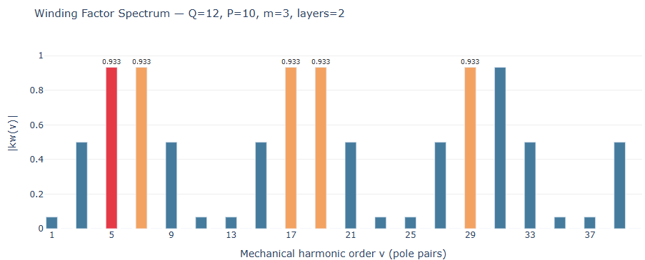
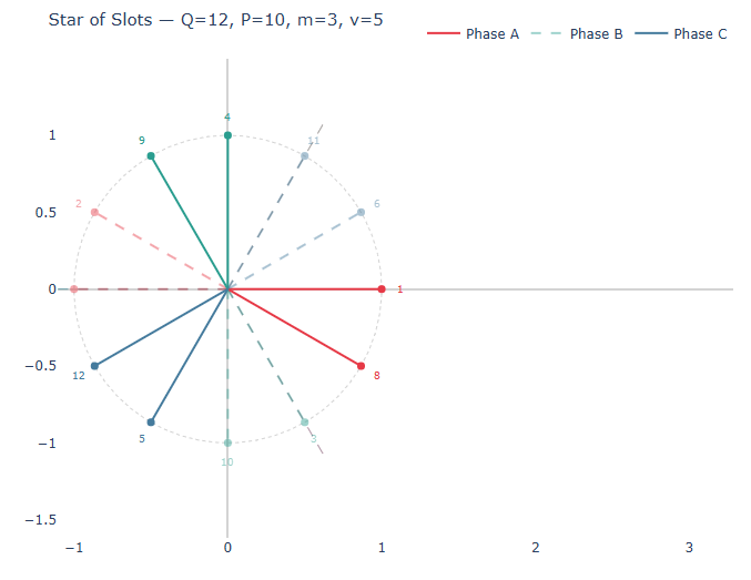
| 12-slot / 10-pole FSCW | 0.933 | Popular in servo drives |
| 12-slot / 8-pole FSCW | 0.866 | Lower kw, but short end-turns |
Choosing a winding configuration
There is no universally optimal winding factor target. High-speed spindle motors favour distributed windings with kw close to 0.966 for smooth torque. Servo and traction motors often use 12s/10p or 12s/14p tooth-coil windings that accept a lower kw1 in exchange for shorter end-turns, easier manufacturing, and natural fault tolerance between phases.
The best approach is to compare configurations at the system level — accounting for copper fill factor, end-turn length, harmonic losses in the rotor, and manufacturing cost — rather than optimising kw in isolation.
Compute winding factor for any slot/pole combination
Visualise the MMF spectrum, star-of-slots diagram, and compare configurations side-by-side.