Coil pitch factor: how a winding captures rotor flux
Pitch factor kp tells you what fraction of the rotor's rotating flux is captured by a single coil. It depends on one thing: how far apart the two coil sides are, measured in electrical degrees.
Electrical angle per slot
A rotor with P poles creates a magnetic flux pattern that completes one full electrical cycle for every pair of poles it passes. As the rotor spins, each stator slot sees this flux wave arrive at a slightly different moment — a phase offset that is fixed by the machine geometry.
This phase offset, called the electrical angle per slot α, is:
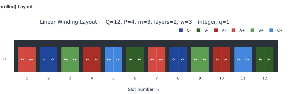
Every slot around the stator is assigned a unique electrical angle based on its position. Slot 1 is the reference at 0°. Slot 2 is at α. Slot 3 is at 2α, and so on. These angles repeat with pole periodicity — after Q/p slots, the pattern of electrical angles starts again from 0°.
Electrical angle per slot: α = (4/2) × (360°/12) = 60° per slot
Slot 1 → 0°, Slot 2 → 60°, Slot 3 → 120°, Slot 4 → 180°, Slot 5 → 240°, Slot 6 → 300°, then repeats (Slot 7 → 360° = 0°, ...)
Coil span and pitch
A coil consists of two conductors — a go side carrying current in one direction and a return side carrying current in the opposite direction — placed in different slots. The number of slots separating them is the coil span y.
The coil span expressed in electrical degrees is:
A full-pitch coil spans exactly one pole pitch — the distance from the centre of one pole to the centre of the adjacent pole. This corresponds to yfp = Q/P slots and always gives β = 180° electrical degrees, regardless of the machine's slot and pole count. A coil spanning less than one pole pitch is called short-pitched or chorded, with β < 180°.
Voltage induced in each coil side
As the rotor flux wave sweeps past the stator, it induces an EMF in every conductor. Because the flux is sinusoidal and rotating, the EMF in a conductor at electrical angle θ takes the form:
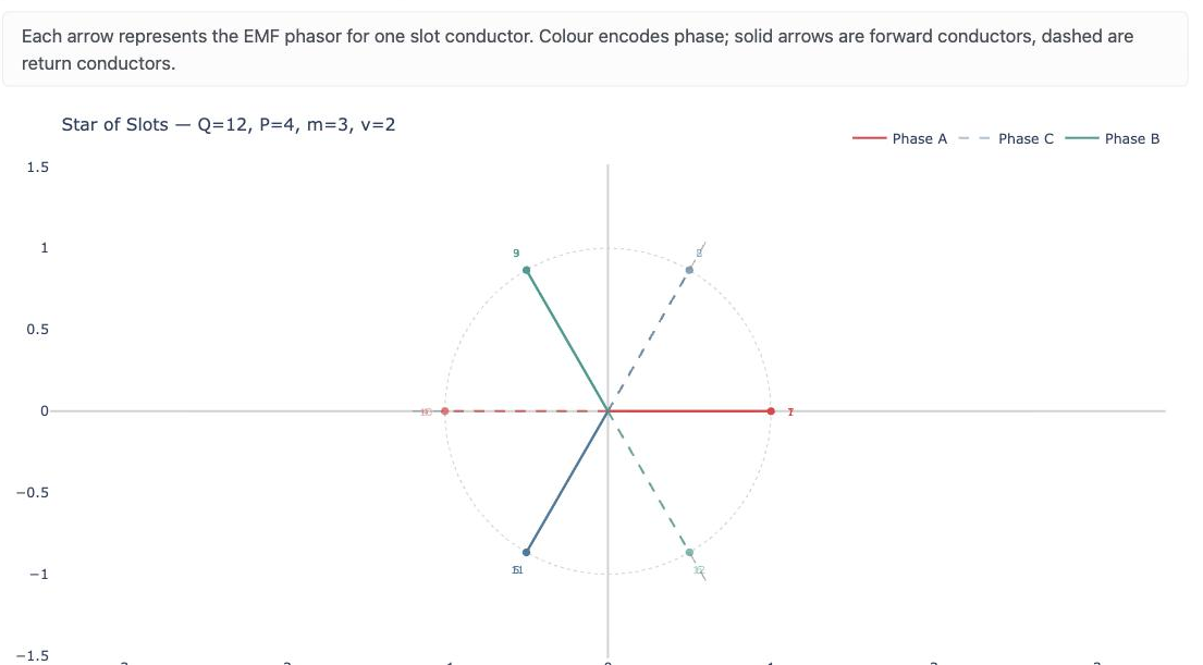
Each conductor produces an EMF phasor whose phase is set by the electrical angle of its slot. Conductors in adjacent slots produce phasors offset by α — they are not in phase with each other, but slightly staggered.
A coil adds the EMF of its two sides in series. The go side contributes its EMF directly; the return side conductor is wound in the opposite direction, so its EMF contribution to the coil is negated. The total coil EMF is therefore:
With the go conductor in a slot at electrical angle 0° (reference) and the return conductor in a slot at electrical angle β:
Worked example: three valid coil pitches for the same machine
Using the 12-slot / 4-pole machine from above (α = 60°), three integer coil spans are possible: y = 1, 2, or 3. Each gives a different β and a different peak coil EMF.
Full pitch — y = 3 slots, β = 180°
ecoil = Ê sin(ωt) − Ê sin(ωt − 180°)
= Ê sin(ωt) − [−Ê sin(ωt)]
= 2Ê sin(ωt) — peak coil EMF = 2Ê
The two coil sides are always in antiphase. Their EMFs reinforce perfectly — this is the maximum a coil can achieve.
Short pitch — y = 2 slots, β = 120°
ecoil = Ê sin(ωt) − Ê sin(ωt − 120°)
Expanding sin(ωt − 120°) = sin(ωt)cos120° − cos(ωt)sin120°:
ecoil = Ê sin(ωt) − Ê[−0.5 sin(ωt) − 0.866 cos(ωt)]
= 1.5Ê sin(ωt) + 0.866Ê cos(ωt)
Peak = Ê √(1.5² + 0.866²) = Ê √3 ≈ 1.732Ê
Ratio to full pitch: 1.732 / 2 = 0.866
Short pitch — y = 1 slot, β = 60°
ecoil = Ê sin(ωt) − Ê sin(ωt − 60°)
Expanding sin(ωt − 60°) = 0.5 sin(ωt) − 0.866 cos(ωt):
ecoil = 0.5Ê sin(ωt) + 0.866Ê cos(ωt)
Peak = Ê √(0.5² + 0.866²) = Ê √1 = Ê
Ratio to full pitch: 1 / 2 = 0.5
All three configurations produce a valid, balanced winding — they simply give different coil EMF amplitudes. The ratio of each amplitude to the full-pitch amplitude is the pitch factor kp.
| Coil span y (slots) | β (electrical degrees) | Peak coil EMF | kp = peak / 2Ê |
|---|---|---|---|
| 3 — full pitch | 180° | 2Ê | 1.000 |
| 2 — short pitch | 120° | 1.732Ê | 0.866 |
| 1 — short pitch | 60° | Ê | 0.500 |
Pitch factor: the general formula
The pattern from the worked examples is exact. For any coil span β, the peak coil EMF can be derived from the vector subtraction of the two conductor phasors:
Dividing by the full-pitch peak 2Ê gives the pitch factor:
An equivalent form uses the chording angle ε — the amount by which the coil falls short of full pitch:
Both forms are identical — use whichever is more natural for your calculation. Textbooks and standards use both conventions.
Pitch factor as effective rotor flux coupling
The pitch factor has a clean physical interpretation: it is the fraction of the rotor's rotating flux that a single coil intercepts compared to what a full-pitch coil would intercept at the same instant.
A full-pitch coil spans exactly 180° electrical. At the moment of peak flux, its two sides straddle the full extent of one pole — go side on the leading edge, return side on the trailing edge. Every field line under the pole threads through the coil. This is the maximum possible flux linkage, and kp = 1.
A short-pitch coil's sides are closer together. The go and return sides are no longer at opposing edges of the pole — they are both partially under the same pole. Some of the flux that passes through one side passes through both sides in the same direction, and the net linkage is reduced. The scaling factor is exactly sin(β/2): the coil links kp × Φmax of the available rotor flux.
Since induced EMF is proportional to the rate of change of flux linkage, the peak EMF of the coil scales by the same factor. A coil with kp = 0.866 generates 13.4% less EMF — and therefore produces 13.4% less torque contribution per ampere — than a full-pitch coil with the same number of turns.
Why use short-pitch coils at all?
The kp formula applies independently to every spatial harmonic of the rotor flux. The pitch factor for the νth harmonic is:
By choosing β carefully, a designer can make kpν = 0 for a specific harmonic — effectively eliminating that harmonic from the winding's EMF and MMF. A coil with β = 150° (5/6 of full pitch) gives kp5 = sin(5 × 75°) = sin(375°) ≈ 0.259 for the 5th harmonic compared to kp1 = sin(75°) = 0.966 for the fundamental: the 5th harmonic is suppressed by over 70% while the fundamental loses less than 3.5%. This is the standard trade-off that makes short-pitching attractive for reducing torque ripple and rotor losses.
End-turn length is a secondary benefit. A full-pitch coil must reach across the full pole pitch on each end of the stator. Chording that span by one or two slots shortens both end-turns, reducing series resistance and end-turn leakage inductance — practical gains that compound at high speeds and tight thermal budgets.
Summary: pitch factor at a glance
| Coil span β | kp | Notes |
|---|---|---|
| 180° (full pitch) | 1.000 | Maximum EMF, longest end-turns |
| 150° (5/6 pitch) | 0.966 | 5th harmonic strongly attenuated |
| 120° (2/3 pitch) | 0.866 | Common in fractional-slot configurations |
| 90° | 0.707 | Significant EMF loss, rarely used |
| 60° | 0.500 | Adjacent-slot coil — extreme chording |
Pitch factor is one of the two components of the overall winding factor kw = kd × kp. The distribution factor kd captures the effect of spreading conductors across multiple slots; the pitch factor kp captures the effect of the coil span. Together they determine how efficiently the winding converts copper current into useful air-gap flux.
Compute pitch factor for any slot/pole combination
Visualise the winding factor spectrum, MMF harmonics, and compare coil pitches side-by-side.