Integer-slot vs fractional-slot windings — when to use each
The choice between distributed and concentrated winding configurations is one of the most consequential decisions in motor design. It affects torque quality, losses, manufacturability, and fault tolerance — often simultaneously pulling in different directions.
The slots-per-pole-per-phase ratio, q
The parameter q — slots per pole per phase — is the single number that classifies any three-phase winding configuration. It is defined as:
When q is a positive integer (1, 2, 3, ...), the winding is an integer-slot distributed winding. When q is a non-integer fraction, the winding is a fractional-slot winding. When q < 1, the coils span only a single tooth — this is the fractional-slot concentrated winding (FSCW), also called a tooth-coil winding.
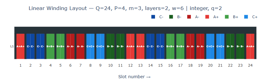
Integer-slot distributed windings
In an integer-slot winding, every pole-phase group contains the same integer number of slots. This produces a periodic, symmetric winding layout that repeats exactly over every pole pitch. The result is a nearly sinusoidal MMF distribution with low harmonic content — particularly for q ≥ 2.
These windings are the standard choice for induction motors, large synchronous generators, and any application where smooth torque and low harmonic losses are the primary requirements. The main disadvantage is long end-turn overhangs — the portions of the winding that extend beyond the stator lamination stack — which consume copper and increase resistance without contributing to torque.
Fractional-slot concentrated windings (FSCW)
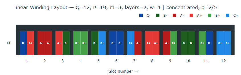
When q < 1, each coil wraps around a single tooth and does not overlap with coils of other phases. This dramatically shortens the end-turns, reducing copper volume and resistive losses. The coils can also be pre-wound and slid onto the teeth — simplifying automated manufacturing significantly.
The most common FSCW configurations for PMSM drives are combinations where the number of slots and poles are close but not equal: 12s/10p, 12s/14p, 9s/8p, and 9s/10p are all widely used in EV traction motors and servo drives. The 12s/10p combination is particularly popular due to its high winding factor (kw1 = 0.933) and good sub-harmonic suppression.
Integer-slot distributed
- Low MMF harmonic content
- Low torque ripple
- Low rotor losses
- Mature, well-understood
- Long end-turns
- Overlapping coils — harder to automate
- No inherent phase isolation
Fractional-slot concentrated
- Short end-turns, less copper
- Non-overlapping — easier to manufacture
- Natural phase isolation (fault tolerant)
- High slot fill factor
- Significant MMF harmonics
- Higher rotor losses
- Sub-harmonics can be problematic
Choosing the right configuration
For high-speed applications — spindle motors, turbochargers, aerospace generators — distributed windings with q = 2 or q = 3 are usually preferred. The lower harmonic content keeps rotor losses manageable at high electrical frequencies, and torque ripple requirements are stringent.
For traction and servo drives operating at moderate speeds with high pole counts, FSCW configurations are often the better choice. The short end-turns improve copper efficiency, the simpler coil geometry enables higher automation, and the natural phase separation between non-overlapping coils provides inherent fault tolerance — an important property in safety-critical automotive applications.
Not all fractional-slot combinations are equal. Some slot/pole pairs produce problematic sub-harmonics (ν < p) with large amplitudes that cause excessive rotor heating. Always check the full MMF spectrum — not just the fundamental winding factor — before committing to a configuration.
Common configurations at a glance
| Configuration | q | Type | kw1 | Typical use |
|---|---|---|---|---|
| 36s/4p | 3 | Distributed | 0.960 | Induction motors |
| 24s/4p | 2 | Distributed | 0.966 | Servo, spindle |
| 12s/10p | 0.4 | FSCW | 0.933 | EV traction, servo |
| 12s/14p | 0.286 | FSCW | 0.933 | EV traction, servo |
| 9s/8p | 0.375 | FSCW | 0.945 | Hub motors |
| 12s/8p | 0.5 | FSCW | 0.866 | General purpose |
Analyse any slot/pole combination interactively
Compare winding factor, MMF harmonics, and conductor layout for integer-slot and fractional-slot configurations side-by-side.