12s/14p vs 12s/10p: a mirror-image winding pair explained
Both configurations use 12 slots with a fractional-slot concentrated winding and share an identical fundamental winding factor of 0.933. Yet they behave quite differently in practice. This article works through five properties — winding distribution, winding factor, MMF harmonics, cogging torque, and operating frequency — to show where and why they diverge.
Starting point: slots per pole per phase
The slots-per-pole-per-phase ratio q classifies the winding configuration. For a three-phase motor (m = 3):
| Parameter | 12s/10p | 12s/14p |
|---|---|---|
| Slots Q | 12 | 12 |
| Poles 2p | 10 | 14 |
| Pole pairs p | 5 | 7 |
| q (slots/pole/phase) | 0.4 | 2/7 ≈ 0.286 |
| Winding type | FSCW (tooth-coil) | FSCW (tooth-coil) |
Both fall well below q = 1, placing them firmly in fractional-slot concentrated winding (FSCW) territory. Each coil wraps a single tooth and does not overlap with coils of adjacent phases — a layout that shortens end-turns and simplifies automated winding.
1. Winding distribution
Although the slot count is the same, the two configurations distribute conductors differently because their pole pitches differ.
| 12s/10p | 12s/14p | |
|---|---|---|
| Slot pitch τs | 30° mech. | 30° mech. |
| Pole pitch τp | 36° mech. | 25.7° mech. |
| Coil span (1 tooth) | 30° mech. = 150° elec. | 30° mech. = 210° elec. |
| Pitch relative to full-pitch | Short-pitched (5/6) | Over-pitched (7/6) |
| Winding base period t = GCD(Q, p) | GCD(12, 5) = 1 | GCD(12, 7) = 1 |
In 12s/10p, each coil spans 30° mechanical against a 36° pole pitch — the coil is short of a full pole pitch by one-sixth (5/6 pitch). In 12s/14p the relationship reverses: the same 30° coil span now exceeds the 25.7° pole pitch, making the winding over-pitched (7/6 pitch).
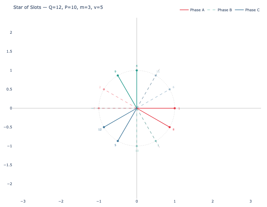
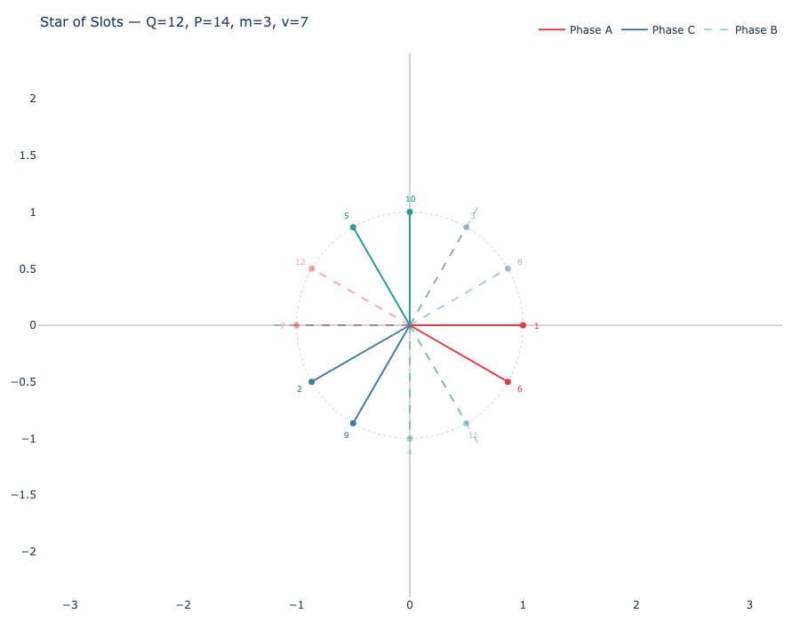
The star-of-slots makes this relationship concrete. For each configuration the electrical angle between consecutive slots is:
For 12s/10p, αe = 5 × 30° = 150°. For 12s/14p, αe = 7 × 30° = 210° ≡ −150° (mod 360°). The 12 slot phasors in both stars land on the same 12 positions — separated by 30° — but they are traversed in opposite rotational directions. The 12s/14p star is the complex conjugate of the 12s/10p star. This single fact explains why every winding factor magnitude is identical between the two configurations while the phase sequence reverses.
2. Winding factor
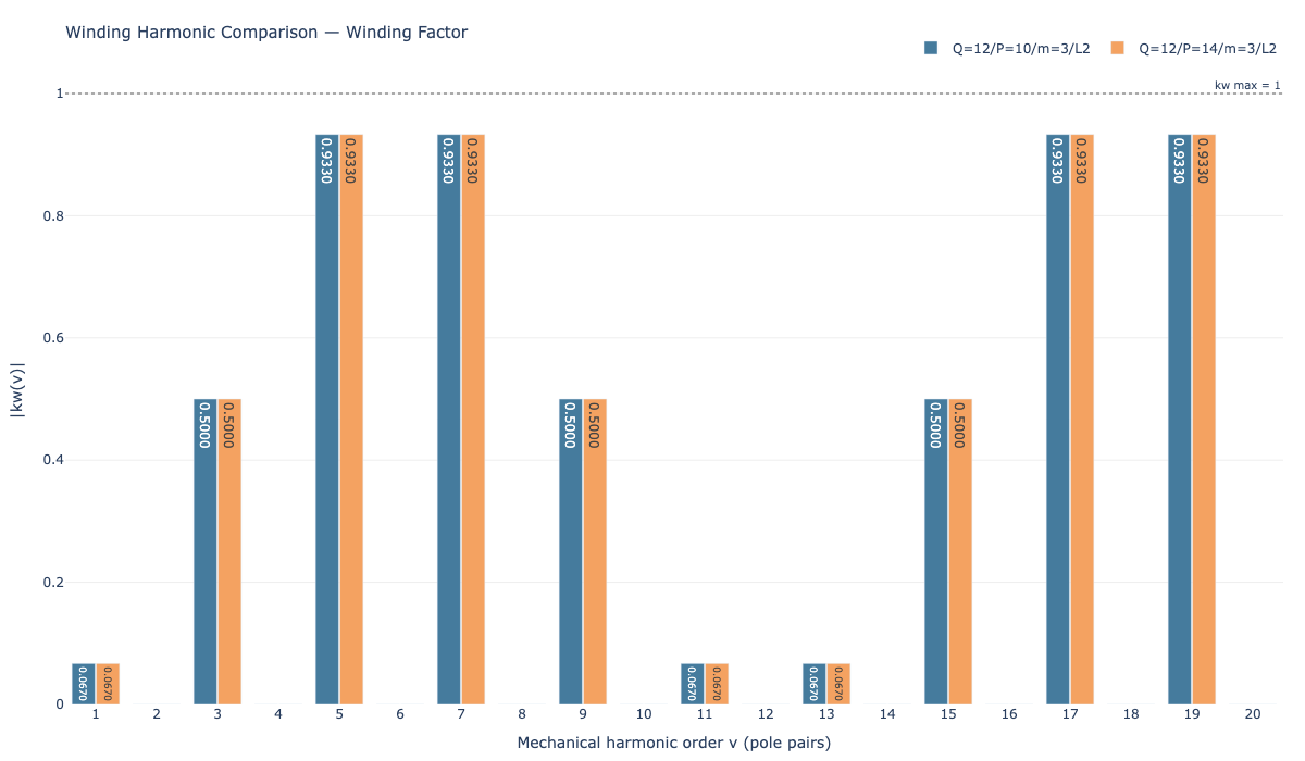
The fundamental winding factor kw1 = 0.933 for both configurations. This is not a coincidence — it follows directly from the complex-conjugate relationship of their stars-of-slots. The magnitudes of the phasor sums, and therefore all winding factor magnitudes, are identical.
The pitch factor for harmonic order ν is kp(ν) = sin(ν × β/2), where β is the coil span in electrical degrees. For the fundamental (ν = p):
The distribution factor from the star-of-slots grouping contributes equally in both cases, giving the same kw1 = 0.933. Where the two configurations do differ is in their harmonic winding factor spectra — specifically, which harmonic order carries the working torque-producing flux:
| Harmonic order ν | kw(ν) — 12s/10p | kw(ν) — 12s/14p | Role |
|---|---|---|---|
| 1 (sub-harmonic) | 0.067 | 0.067 | Loss-producing in both |
| 5 | 0.933 — working | 0.933 — parasitic | Working for 12s/10p; large parasitic for 12s/14p |
| 7 | 0.933 — parasitic | 0.933 — working | Large parasitic for 12s/10p; working for 12s/14p |
| 11 | 0.067 | 0.067 | Minor, loss-producing |
| 13 | 0.067 | 0.067 | Minor, loss-producing |
The fundamental insight: 12s/10p and 12s/14p have identical winding factor spectra. The only difference is the label — what is the "working harmonic" in one is a large parasitic in the other.
3. MMF harmonics
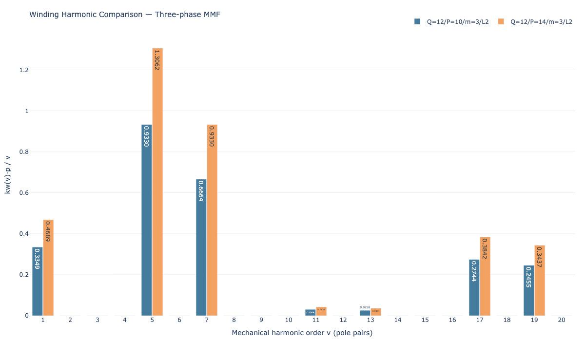
The air-gap magnetomotive force contains spatial harmonics at every order ν where the winding factor is non-zero. For a balanced three-phase winding, triplen harmonics cancel and even orders are suppressed, leaving the odd, non-triplen sequence: 1, 5, 7, 11, 13, 17, 19, …
The amplitude of the νth MMF harmonic scales as:
Because kw(5) = kw(7) = 0.933 for both configurations, the ν = 5 and ν = 7 components are close in amplitude — differing only by their 1/ν decay factor. This means each configuration carries a large parasitic MMF harmonic that is nearly as strong as the working fundamental.
The consequence is rotor losses. A parasitic field harmonic rotating at a different speed than the rotor sweeps across the permanent magnets and back-iron, inducing eddy currents. The frequency that the rotor sees from the parasitic harmonic is:
| 12s/10p | 12s/14p | |
|---|---|---|
| Working harmonic p | 5 | 7 |
| Dominant parasitic harmonic ν | 7 | 5 |
| Parasitic frequency seen by rotor | |7−5| × fmech = 2fmech | |5−7| × fmech = 2fmech |
| Sub-harmonic ν = 1 (rotor frequency) | |1−5| × fmech = 4fmech | |1−7| × fmech = 6fmech |
The dominant parasitic (ν = 7 for 12s/10p, ν = 5 for 12s/14p) produces rotor eddy currents at exactly 2× the mechanical rotation frequency in both cases — the rotor loss from this harmonic is symmetric between the two configurations at the same mechanical speed. The sub-harmonic at ν = 1 is smaller in amplitude (kw = 0.067) but sweeps the rotor faster: at 6× mechanical frequency for 12s/14p versus 4× for 12s/10p. At very high speeds this difference can become significant.
The practical implication: neither configuration is clearly superior in terms of the dominant harmonic rotor loss. The choice between them does not hinge on MMF harmonic quality — it hinges on cogging torque and operating frequency, covered next.
4. Cogging torque
Cogging torque arises from the tendency of the rotor magnets to align with stator teeth as the rotor turns. The number of cogging torque cycles per revolution is determined by the lowest common multiple of slot count and pole count:
| 12s/10p | 12s/14p | |
|---|---|---|
| LCM(Q, 2p) | LCM(12, 10) = 60 | LCM(12, 14) = 84 |
| Cogging cycles per revolution | 60 | 84 (+40%) |
| Angular period per cogging pulse | 6.0° | 4.3° |
| Relative cogging amplitude | Higher | Lower |
A higher LCM means the same total cogging energy is distributed over more cycles — each pulse is smaller. The 12s/14p configuration produces 40% more cogging cycles per revolution, giving it inherently lower cogging torque amplitude without any additional mitigation (skewing, magnet shaping) needed.
More cogging cycles means the energy is distributed over more periods, reducing the peak amplitude of each pulse. This is a direct consequence of the higher LCM — no additional mitigation such as skewing or magnet shaping is required to achieve it.
5. Operating frequency
The electrical frequency of a motor spinning at n revolutions per minute is:
Because 12s/14p has p = 7 pole pairs versus p = 5 for 12s/10p, it operates at 40% higher electrical frequency for the same mechanical speed.
| Speed (rpm) | fe — 12s/10p (p=5) | fe — 12s/14p (p=7) |
|---|---|---|
| 1,000 | 83 Hz | 117 Hz |
| 3,000 | 250 Hz | 350 Hz |
| 6,000 | 500 Hz | 700 Hz |
| 10,000 | 833 Hz | 1,167 Hz |
Higher electrical frequency has direct consequences for two loss mechanisms:
Iron losses in the stator laminations depend on both frequency and peak flux density, with hysteresis and eddy current components behaving differently across the operating range. The 40% higher electrical frequency of 12s/14p means core loss must be evaluated carefully — the actual penalty depends on lamination grade, thickness, and the flux density at the operating point, and cannot be read off from frequency alone. You can compare a lamination grade’s core loss at both electrical frequencies in the electrical steel tool.
Inverter switching frequency must scale with the electrical frequency to maintain acceptable current ripple. Higher fe requires either faster switching (more switching losses) or accepts greater current ripple at the same switching frequency.
Summary
| Property | 12s/10p | 12s/14p |
|---|---|---|
| Pole pairs p | 5 | 7 |
| q (slots/pole/phase) | 0.4 | 2/7 ≈ 0.286 |
| Coil pitch | Short (5/6), 150° elec. | Over (7/6), 210° elec. |
| Fundamental kw1 | 0.933 | 0.933 |
| Working harmonic | ν = 5 | ν = 7 |
| Dominant parasitic harmonic | ν = 7 | ν = 5 |
| Dominant parasitic rotor frequency | 2× fmech | 2× fmech |
| Cogging cycles/revolution | 60 | 84 (lower amplitude) |
| Electrical frequency (same RPM) | fe = 5n/60 | fe = 7n/60 (+40%) |
| Iron losses (same RPM, same B) | Requires evaluation — depends on lamination grade, thickness, and operating flux density | |
Compare 12s/14p and 12s/10p interactively
Star-of-slots, winding factor spectrum, MMF harmonics, and conductor layout — side by side.